20 Graphs, Networks, and Trees
Table of contents
Graphical representations are widely used for displaying relations among informational units because they help readers to visualize those relations and hence to understand them better. Two general types of graphical representations may be distinguished.
- Graphs, in the strictly mathematical sense, consist of points, often called nodes or vertices, and connections among them, called arcs, or under certain conditions, edges. Among the various types of graphs are networks and trees. Graphs generally and networks in particular are dealt with directly below. Trees are dealt with separately in sections 20.2 Trees and 20.3 Another Tree Notation.87
- Charts, which typically plot data in two or more dimensions, including plots with orthogonal or radial axes, bar charts, pie charts, and the like. These can be described using the elements defined in the module for figures and graphics; see chapter 15 Tables, Formulæ, Graphics, and Notated Music.
Among the types of qualitative relations often represented by graphs are organizational hierarchies, flow charts, genealogies, semantic networks, transition networks, grammatical relations, tournament schedules, seating plans, and directions to people's houses. In developing recommendations for the encoding of graphs of various types, we have relied on their formal mathematical definitions and on the most common conventions for representing them visually. However, it must be emphasized that these recommendations do not provide for the full range of possible graphical representations, and deal only partially with questions of design, layout, and placement.
TEI: Graphs and Digraphs⚓︎20.1 Graphs and Digraphs
Broadly speaking, graphs can be divided into two types: undirected and directed. An undirected graph is a set of nodes (or vertices) together with a set of pairs of those vertices, called arcs or edges. Each node in an arc of an undirected graph is said to be incident with that arc, and the two vertices (nodes) which make up an arc are said to be adjacent. An directed graph is like an undirected graph except that the arcs are ordered pairs of nodes. In the case of directed graphs, the term edge is not used; moreover, each arc in a directed graph is said to be adjacent from the node from which the arc emanates, and adjacent to the node to which the arc is directed. We use the element graph to encode graphs as a whole, node to encode nodes or vertices, and arc to encode arcs or edges; arcs can also be encoded by attributes on the node element. These elements have the following descriptions and attributes:
- graph (graph) encodes a graph, which is a collection of nodes, and arcs which connect the nodes.
- node (node) encodes a node, a possibly labeled point in a graph.
- arc (arc) encodes an arc, the connection from one node to another in a graph.
Before proceeding, some additional terminology may be helpful. We define a path in a graph as a sequence of nodes n1, ..., nk such that there is an arc from each ni to ni+1 in the sequence. A cyclic path, or cycle is a path leading from a particular node back to itself. A graph that contains at least one cycle is said to be cyclic; otherwise it is acyclic. We say, finally, that a graph is connected if there is a path from some node to every other node in the graph; any graph that is not connected is said to be disconnected.
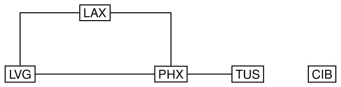
Here is an example of an undirected, cyclic disconnected graph, in which the nodes are annotated with three-letter codes for airports, and the arcs connecting the nodes are represented by horizontal and vertical lines, with 90 degree bends used simply to avoid having to draw diagonal lines.
order="5" size="4">
<label>Airline Connections in Southwestern USA</label>
<node xml:id="LAX" degree="2">
<label>LAX</label>
</node>
<node xml:id="LVG" degree="2">
<label>LVG</label>
</node>
<node xml:id="PHX" degree="3">
<label>PHX</label>
</node>
<node xml:id="TUS" degree="1">
<label>TUS</label>
</node>
<node xml:id="CIB" degree="0">
<label>CIB</label>
</node>
<arc from="#LAX" to="#LVG"/>
<arc from="#LAX" to="#PHX"/>
<arc from="#LVG" to="#PHX"/>
<arc from="#PHX" to="#TUS"/>
</graph>
The first child element of graph may be a label to record a label for the graph; similarly, the label child of each node element records the labels of that node. The order and size attributes on the graph element record the number of nodes and number of arcs in the graph respectively; these values are optional (since they can be computed from the rest of the graph), but if they are supplied, they must be consistent with the rest of the encoding. They can thus be used to help check that the graph has been encoded and transmitted correctly. The degree attribute on the node elements record the number of arcs that are incident with that node. It is optional (because redundant), but can be used to help in validity checking: if a value is given, it must be consistent with the rest of the information in the graph. Finally, the from and to attributes on the arc elements provide pointers to the nodes connected by those arcs. Since the graph is undirected, no directionality is implied by the use of the from and to attributes; the values of these attributes could be interchanged in each arc without changing the graph.
order="5" size="4">
<label>Airline Connections in Southwestern USA</label>
<node xml:id="LAX2" degree="2"
adj="#LVG2 #PHX2">
<label>LAX2</label>
</node>
<node xml:id="LVG2" degree="2"
adj="#LAX2 #PHX2">
<label>LVG2</label>
</node>
<node xml:id="PHX2" degree="3"
adj="#LAX2 #LVG2 #TUS2">
<label>PHX2</label>
</node>
<node xml:id="TUS2" degree="1" adj="#PHX2">
<label>TUS2</label>
</node>
<node xml:id="CIB2" degree="0">
<label>CIB2</label>
</node>
</graph>
order="5" size="4">
<label>Airline Connections in Southwestern USA</label>
<node xml:id="LAX3" degree="2"
adj="#LVG3 #PHX3">
<label>LAX3</label>
</node>
<node xml:id="LVG3" degree="2" adj="#PHX3">
<label>LVG3</label>
</node>
<node xml:id="PHX3" degree="3" adj="#TUS3">
<label>PHX3</label>
</node>
<node xml:id="TUS3" degree="1">
<label>TUS3</label>
</node>
<node xml:id="CIB3" degree="0">
<label>CIB3</label>
</node>
</graph>
Although in many cases the arc element is redundant (since arcs can be described using the adjacency attributes of their adjacent nodes), it has nevertheless been included in this module, in order to allow the convenient specification of identifiers, display or rendition information, and labels for each arc (using the attributes xml:id, rend, and a child label element).
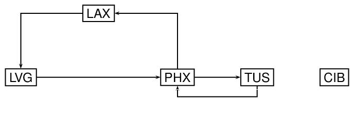
Next, let us modify the preceding graph by adding directionality to the arcs. Specifically, we now think of the arcs as specifying selected routes from one airport to another, as indicated by the direction of the arrowheads in the following diagram.
order="5" size="5">
<label>Selected Airline Routes in Southwestern USA</label>
<node xml:id="LAX4" inDegree="1"
outDegree="1">
<label>LAX4</label>
</node>
<node xml:id="LVG4" inDegree="1"
outDegree="1">
<label>LVG4</label>
</node>
<node xml:id="PHX4" inDegree="2"
outDegree="2">
<label>PHX4</label>
</node>
<node xml:id="TUS4" inDegree="1"
outDegree="1">
<label>TUS4</label>
</node>
<node xml:id="CIB4" inDegree="0"
outDegree="0">
<label>CIB4</label>
</node>
<arc from="#LAX4" to="#LVG4"/>
<arc from="#LVG4" to="#PHX4"/>
<arc from="#PHX4" to="#LAX4"/>
<arc from="#PHX4" to="#TUS4"/>
<arc from="#TUS4" to="#PHX4"/>
</graph>
order="5" size="5">
<label>Selected Airline Routes in Southwestern USA</label>
<node xml:id="LAX5" inDegree="1"
outDegree="1" adjTo="#LVG5" adjFrom="#PHX5">
<label>LAX5</label>
</node>
<node xml:id="LVG5" inDegree="1"
outDegree="1" adjFrom="#LAX5" adjTo="#PHX5">
<label>LVG5</label>
</node>
<node xml:id="PHX5" inDegree="2"
outDegree="2" adjTo="#LAX5 #TUS" adjFrom="#LVG5 #TUS5">
<label>PHX5</label>
</node>
<node xml:id="TUS5" inDegree="1"
outDegree="1" adjTo="#PHX5" adjFrom="#PHX5">
<label>TUS5</label>
</node>
<node xml:id="CIB5" inDegree="0"
outDegree="0">
<label>CIB5</label>
</node>
</graph>
order="5" size="5">
<label>Selected Airline Routes in Southwestern USA</label>
<node xml:id="LAX6">
<label>LAX6</label>
</node>
<node xml:id="LVG6">
<label>LVG6</label>
</node>
<node xml:id="PHX6">
<label>PHX6</label>
</node>
<node xml:id="TUS6">
<label>TUS6</label>
</node>
<node xml:id="CIB6">
<label>CIB6</label>
</node>
<arc from="#LAX6" to="#LVG6">
<label>SW117</label>
</arc>
<arc from="#LVG6" to="#PHX6">
<label>SW711</label>
</arc>
<arc from="#PHX6" to="#LAX6">
<label>AA218</label>
</arc>
<arc from="#PHX6" to="#TUS6">
<label>AW229</label>
</arc>
<arc from="#TUS6" to="#PHX6">
<label>AW225</label>
</arc>
</graph>
TEI: Transition Networks⚓︎20.1.1 Transition Networks
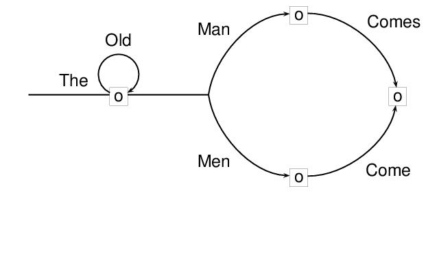
For encoding transition networks and other kinds of directed graphs in which distinctions among types of nodes must be made, the type attribute is provided for node elements. In the following example, the initial and final nodes (or states) of the network are distinguished. It can be understood as accepting the set of strings obtained by traversing it from its initial node to its final node, and concatenating the labels.
xml:id="SS8" order="5" size="6">
<label>(8)</label>
<node xml:id="Q0" inDegree="0"
outDegree="1" type="initial"/>
<node xml:id="Q1" inDegree="2"
outDegree="3"/>
<node xml:id="Q2" inDegree="1"
outDegree="1"/>
<node xml:id="Q3" inDegree="1"
outDegree="1"/>
<node xml:id="Q4" inDegree="2"
outDegree="0" type="final"/>
<arc from="#Q0" to="#Q1">
<label>THE</label>
</arc>
<arc from="#Q1" to="#Q1">
<label>OLD</label>
</arc>
<arc from="#Q1" to="#Q2">
<label>MAN</label>
</arc>
<arc from="#Q1" to="#Q3">
<label>MEN</label>
</arc>
<arc from="#Q2" to="#Q4">
<label>COMES</label>
</arc>
<arc from="#Q3" to="#Q4">
<label>COME</label>
</arc>
</graph>
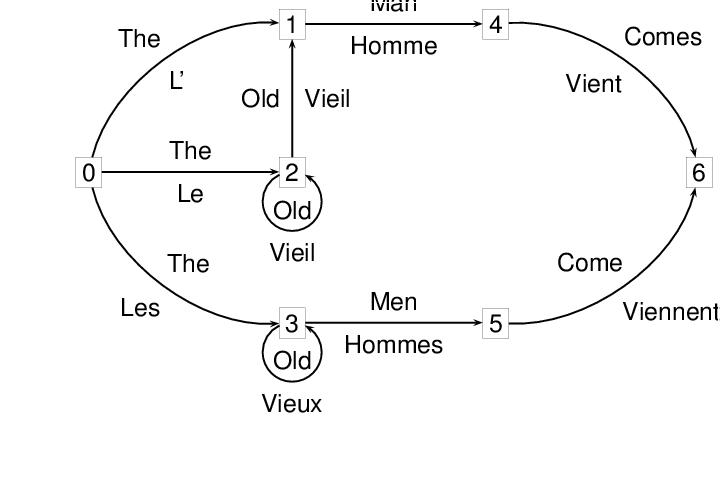
A finite state transducer has two labels on each arc, and can be thought of as representing a mapping from one sequence of labels to the other. The following example represents a transducer for translating the English strings accepted by the network in the preceding example into French. The nodes have been annotated with numbers, for convenience.
<node xml:id="T0" inDegree="0"
outDegree="3" type="initial">
<label>0</label>
</node>
<node xml:id="T1" inDegree="2"
outDegree="1">
<label>1</label>
</node>
<node xml:id="T2" inDegree="2"
outDegree="2">
<label>2</label>
</node>
<node xml:id="T3" inDegree="2"
outDegree="2">
<label>3</label>
</node>
<node xml:id="T4" inDegree="1"
outDegree="1">
<label>4</label>
</node>
<node xml:id="T5" inDegree="1"
outDegree="1">
<label>5</label>
</node>
<node xml:id="T6" inDegree="2"
outDegree="0" type="final">
<label>6</label>
</node>
<arc from="#T0" to="#T1">
<label>THE</label>
<label>L'</label>
</arc>
<arc from="#T0" to="#T2">
<label>THE</label>
<label>LE</label>
</arc>
<arc from="#T0" to="#T3">
<label>THE</label>
<label>LES</label>
</arc>
<arc from="#T1" to="#T4">
<label>MAN</label>
<label>HOMME</label>
</arc>
<arc from="#T2" to="#T1">
<label>OLD</label>
<label>VIEIL</label>
</arc>
<arc from="#T2" to="#T2">
<label>OLD</label>
<label>VIEIL</label>
</arc>
<arc from="#T3" to="#T3">
<label>OLD</label>
<label>VIEUX</label>
</arc>
<arc from="#T3" to="#T5">
<label>MEN</label>
<label>HOMMES</label>
</arc>
<arc from="#T4" to="#T6">
<label>COMES</label>
<label>VIENT</label>
</arc>
<arc from="#T5" to="#T6">
<label>COME</label>
<label>VIENNENT</label>
</arc>
</graph>
TEI: Family Trees⚓︎20.1.2 Family Trees
The next example provides an encoding a portion of a family tree88 in which nodes are used to represent individuals and parents of individuals, and arcs are used to represent common parentage and descent links. Let us suppose, further, that information about individuals is contained in feature structures, which are contained in feature-structure libraries elsewhere (see 19.4 Feature Libraries and Feature-Value Libraries). We can use the value attribute on node elements to point to those feature structures. In this particular representation of the graph, nodes representing females are framed by ovals, nodes representing males are framed by boxes, and nodes representing parents are framed by diamonds.

size="12">
<node xml:id="KATHR"
value="http://example.com/russell-fs/tei/kr1" inDegree="0" outDegree="1">
<label>Katherine</label>
</node>
<node xml:id="AMBER"
value="http://example.com/russell-fs/tei/ar1" inDegree="0" outDegree="1">
<label>Amberley</label>
</node>
<node xml:id="KAR" inDegree="2"
outDegree="3">
<label>K+A</label>
</node>
<node xml:id="BERTR"
value="http://example.com/russell-fs/tei/br1" inDegree="1" outDegree="2">
<label>Bertrand</label>
</node>
<node xml:id="PETER"
value="http://example.com/russell-fs/tei/pr1" inDegree="0" outDegree="1">
<label>Peter</label>
</node>
<node xml:id="DORAR"
value="http://example.com/russell-fs/tei/dr1" inDegree="0" outDegree="1">
<label>Dora</label>
</node>
<node xml:id="PBR" inDegree="2"
outDegree="1">
<label>P+B</label>
</node>
<node xml:id="DBR" inDegree="2"
outDegree="2">
<label>D+B</label>
</node>
<node xml:id="FRANR"
value="http://example.com/russell-fs/tei/fr1" inDegree="1" outDegree="0">
<label>Frank</label>
</node>
<node xml:id="RACHR"
value="http://example.com/russell-fs/tei/rr1" inDegree="1" outDegree="0">
<label>Rachel</label>
</node>
<node xml:id="CONRR"
value="http://example.com/russell-fs/tei/cr1" inDegree="1" outDegree="0">
<label>Conrad</label>
</node>
<node xml:id="KATER"
value="http://example.com/russell-fs/tei/kr2" inDegree="1" outDegree="0">
<label>Kate</label>
</node>
<node xml:id="JOHNR"
value="http://example.com/russell-fs/tei/jr1" inDegree="1" outDegree="0">
<label>John</label>
</node>
<arc from="#KATHR" to="#KAR">
<label>Mo</label>
</arc>
<arc from="#AMBER" to="#KAR">
<label>Fa</label>
</arc>
<arc from="#KAR" to="#BERTR">
<label>So</label>
</arc>
<arc from="#KAR" to="#FRANR">
<label>So</label>
</arc>
<arc from="#KAR" to="#RACHR">
<label>Da</label>
</arc>
<arc from="#PETER" to="#PBR">
<label>Mo</label>
</arc>
<arc from="#BERTR" to="#PBR">
<label>Fa</label>
</arc>
<arc from="#PBR" to="#CONRR">
<label>So</label>
</arc>
<arc from="#DORAR" to="#DBR">
<label>Mo</label>
</arc>
<arc from="#BERTR" to="#DBR">
<label>Fa</label>
</arc>
<arc from="#DBR" to="#KATER">
<label>Da</label>
</arc>
<arc from="#DBR" to="#JOHNR">
<label>So</label>
</arc>
</graph>
TEI: Historical Interpretation⚓︎20.1.3 Historical Interpretation
For our final example, we represent graphically the relationships among various geographic areas mentioned in a seventeenth-century Scottish document. The document itself is a ‘sasine’, which records a grant of land from the earl of Argyll to one Donald McNeill, and reads in part as follows (abbreviations have been expanded silently, and ‘[...]’ marks illegible passages):
Item instrument of Sasine given the said Hector Mcneil confirmed and dated 28 May 1632 [...] at Edinburgh upon the 15 June 1632
Item ane charter granted by Archibald late earl of Argyle and Donald McNeill of Gallachalzie wh makes mention that ... the said late Earl yields and grants to the said Donald MacNeill ...
All and hail the two merk land of old extent of Gallachalzie with the pertinents by and in the lordship of Knapdale within the sherrifdome of Argyll
[description of other lands granted follows ...]
This Charter is dated at Inverary the 15th May 1669
In this example, we are concerned with the land and pertinents (i.e. accompanying sources of revenue) described as ‘the two merk land of old extent of Gallachalzie with the pertinents by and in the lordship of Knapdale within the sherrifdom of Argyll’.
The passage concerns the following pieces of land:
- the Earl of Argyll's land (i.e. the lands granted by this clause of the sasine)
- two mark of land in Gallachalzie
- the pertinents for this land
- the Lordship of Knapdale
- the sherrifdom of Argyll
We will represent these geographic entities as nodes in a graph. Arcs in the graph will represent the following relationships among them:
- containment (INCLUDE)
- location within (IN)
- contiguity (BY)
- constituency (PART OF)
Note that these relationships are logically related: ‘include’ and ‘in’, for example, are inverses of each other: the Earl of Argyll's land includes the parcel in Gallachalzie, and the parcel is therefore in the Earl of Argyll's land. Given an explicit set of inference rules, an appropriate application could use the graph we are constructing to infer the logical consequences of the relationships we identify.
Let us assume that feature-structure analyses are available which describe Gallachalzie, Knapdale, and Argyll. We will link to those feature structures using the value attribute on the nodes representing those places. However, there may be some uncertainty as to which noun phrase is modified by the phrase ‘within the sheriffdome of Argyll’: perhaps the entire lands (land and pertinents) are in Argyll, perhaps just the pertinents are, or perhaps only Knapdale is (together with the portion of the pertinents which is in Knapdale). We will represent all three of these interpretations in the graph; they are, however, mutually exclusive, which we represent using the exclude attribute defined in chapter 17 Linking, Segmentation, and Alignment.89
We represent the graph and its encoding as follows, where the dotted lines in the graph indicate the mutually exclusive arcs; in the encoding, we use the exclude attribute to indicate those arcs.
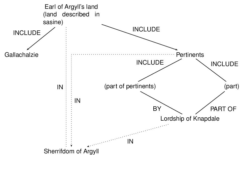
- the Earl of Argyll's land includes (the parcel of land in) Gallachalzie
- the Earl of Argyll's land includes the pertinents of that parcel
- the pertinents are (in part) by the Lordship of Knapdale
- the pertinents are (in part) part of the Lordship of Knapdale
- the Earl of Argyll's land, or the pertinents, or the Lordship of Knapdale, is in the Sherrifdom of Argyll
<node xml:id="EARL">
<label>Earl of Argyll's land</label>
</node>
<node xml:id="GALL"
value="http://example.com/people/scots#gall">
<label>Gallachalzie</label>
</node>
<node xml:id="PERT">
<label>Pertinents</label>
</node>
<node xml:id="PER1">
<label>Pertinents part</label>
</node>
<node xml:id="PER2">
<label>Pertinents part</label>
</node>
<node xml:id="KNAP"
value="http://example.com/people/scots#knapfs">
<label>Lordship of Knapdale</label>
</node>
<node xml:id="ARGY"
value="http://example.com/people/scots#argyfs">
<label>Sherrifdome of Argyll</label>
</node>
<arc xml:id="EARLGALL" from="#EARL"
to="#GALL">
<label>INCLUDE</label>
</arc>
<arc xml:id="EARLARGY" from="#EARL"
to="#ARGY" exclude="#PERTARGY #KNAPARGY">
<label>IN</label>
</arc>
<arc xml:id="EARLPERT" from="#EARL"
to="#PERT">
<label>INCLUDE</label>
</arc>
<arc xml:id="PERTPER1" from="#PERT"
to="#PER1">
<label>INCLUDE</label>
</arc>
<arc xml:id="PERTPER2" from="#PERT"
to="#PER2">
<label>INCLUDE</label>
</arc>
<arc xml:id="PERTARGY" from="#PERT"
to="#ARGY" exclude="#EARLARGY #KNAPARGY">
<label>IN</label>
</arc>
<arc xml:id="PER1KNAP" from="#PER1"
to="#KNAP">
<label>BY</label>
</arc>
<arc xml:id="PER2KNAP" from="#PER2"
to="#KNAP">
<label>PART OF</label>
</arc>
<arc xml:id="KNAPARGY" from="#KNAP"
to="#ARGY" exclude="#EARLARGY #PERTARGY">
<label>IN</label>
</arc>
</graph>
TEI: Trees⚓︎20.2 Trees
A tree is a connected acyclic graph. That is, it is possible in a tree graph to follow a path from any vertex to any other vertex, but there are no paths that lead from any vertex to itself. A rooted tree is a directed graph based on a tree; that is, the arcs in the graph correspond to the arcs of a tree such that there is exactly one node, called the root, for which there is a path from that node to all other nodes in the graph. For our purposes, we may ignore all trees except for rooted trees, and hence we shall use the tree element for rooted trees, and the root element for its root. The nodes adjacent to a given node are called its children, and the node adjacent from a given node is called its parent. Nodes with both a parent and children are called internal nodes, for which we use the iNode element. A node with no children is tagged as a leaf. If the children of a node are ordered from left to right, then we say that that node is ordered. If all the nodes of a tree are ordered, then we say that the tree is an ordered tree. If some of the nodes of a tree are ordered and others are not, then the tree is a partially ordered tree. The ordering of nodes and trees may be specified by an attribute; we take the default ordering for trees to be ordered, that roots inherit their ordering from the trees in which they occur, and internal nodes inherit their ordering from their parents. Finally, we permit a node to be specified as following other nodes, which (when its parent is ordered) it would be assumed to precede, giving rise to crossing arcs. The elements used for the encoding of trees have the following descriptions and attributes.
- tree (tree) encodes a tree, which is made up of a root, internal nodes, leaves, and arcs
from root to leaves.
arity gives the maximum number of children of the root and internal nodes of the tree. ord (ordered) indicates whether or not the tree is ordered, or if it is partially ordered. order gives the order of the tree, i.e., the number of its nodes. - root (root node) represents the root node of a tree.
value identifies the root node of the network by pointing to a feature structure or other analytic element. children identifies the elements which are the children of the root node. ord (ordered) indicates whether or not the root is ordered. outDegree gives the out degree of the root, the number of its children. - iNode (intermediate (or internal) node) represents an intermediate (or internal) node of
a tree.
value indicates an intermediate node, which is a feature structure or other analytic element. children provides a list of identifiers of the elements which are the children of the intermediate node. parent provides the identifier of the element which is the parent of this node. ord (ordered) indicates whether or not the internal node is ordered. follow provides the identifier of an element which this node follows. outDegree gives the out degree of an intermediate node, the number of its children. - leaf (leaf) encodes the leaves (terminal nodes) of a tree.
value provides a pointer to a feature structure or other analytic element. parent provides the identifier of parent of a leaf. follow provides an identifier of an element which this leaf follows.
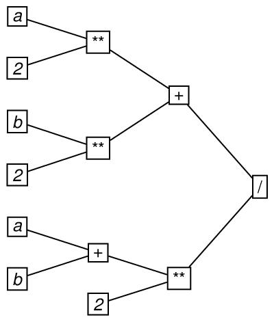
Here is an example of a tree. It represents the order in which the operators of addition
(symbolized by +), exponentiation (symbolized by **) and division (symbolized by /) are applied in evaluating the arithmetic formula ((a**2)+(b**2))/((a+b)**2). In drawing the graph, the root is placed on the far right, and directionality is
presumed to be to the left.
<root xml:id="G-DIV1"
children="#PLU1 #EXP1">
<label>/</label>
</root>
<iNode xml:id="PLU1" parent="#G-DIV1"
children="#EXP2 #EXP3">
<label>+</label>
</iNode>
<iNode xml:id="EXP1" parent="#G-DIV1"
children="#PLU2 #NUM2.3">
<label>**</label>
</iNode>
<iNode xml:id="EXP2" parent="#PLU1"
children="#VARA1 #NUM2.1">
<label>**</label>
</iNode>
<iNode xml:id="EXP3" parent="#PLU1"
children="#VARB1 #NUM2.2">
<label>**</label>
</iNode>
<iNode xml:id="PLU2" parent="#EXP1"
children="#VARA2 #VARB2">
<label>+</label>
</iNode>
<leaf xml:id="VARA1" parent="#EXP2">
<label>a</label>
</leaf>
<leaf xml:id="NUM2.1" parent="#EXP2">
<label>2</label>
</leaf>
<leaf xml:id="VARB1" parent="#EXP3">
<label>b</label>
</leaf>
<leaf xml:id="NUM2.2" parent="#EXP3">
<label>2</label>
</leaf>
<leaf xml:id="VARA2" parent="#PLU2">
<label>a</label>
</leaf>
<leaf xml:id="VARB2" parent="#PLU2">
<label>b</label>
</leaf>
<leaf xml:id="NUM2.3" parent="#EXP1">
<label>2</label>
</leaf>
</tree>
In this encoding, the arity attribute represents the arity of the tree, which is the greatest value of the outDegree attribute for any of the nodes in the tree. If, as in this case, arity is 2, we say that the tree is a binary tree.
+ nodes does not affect the arithmetic result in this case, we could represent in this
tree all of the arithmetically equivalent formulas involving its leaves, by specifying
the attribute ord as false on those two iNode elements, the attribute ord as true on the root and other iNode elements, and the attribute ord as partial on the tree element, as follows.
order="13">
<root xml:id="divi1" ord="true"
children="#plu1 #exp1">
<label>/</label>
</root>
<iNode xml:id="plu1" ord="false"
parent="#divi1" children="#exp2 #exp3">
<label>+</label>
</iNode>
<iNode xml:id="exp1" ord="true"
parent="#divi1" children="#plu2 #num2.3">
<label>**</label>
</iNode>
<iNode xml:id="exp2" ord="true"
parent="#plu1" children="#vara1 #num2.1">
<label>**</label>
</iNode>
<iNode xml:id="exp3" ord="true"
parent="#plu1" children="#varb1 #num2.2">
<label>**</label>
</iNode>
<iNode xml:id="plu2" ord="false"
parent="#exp1" children="#vara2 #varb2">
<label>+</label>
</iNode>
<leaf xml:id="vara1" parent="#exp2">
<label>a</label>
</leaf>
<leaf xml:id="num2.1" parent="#exp2">
<label>2</label>
</leaf>
<leaf xml:id="varb1" parent="#exp3">
<label>b</label>
</leaf>
<leaf xml:id="num2.2" parent="#exp3">
<label>2</label>
</leaf>
<leaf xml:id="vara2" parent="#plu2">
<label>a</label>
</leaf>
<leaf xml:id="varb2" parent="#plu2">
<label>b</label>
</leaf>
<leaf xml:id="num2.3" parent="#exp1">
<label>2</label>
</leaf>
</tree>
This encoding represents all of the following:
((a**2)+(b**2))/((a+b)**2)((b**2)+(a**2))/((a+b)**2)((a**2)+(b**2))/((b+a)**2)((b**2)+(a**2))/((a+b)**2)
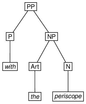
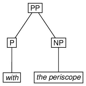
Linguistic phrase structure is very commonly represented by trees. Here is an example of phrase structure represented by an ordered tree with its root at the top, and a possible encoding.

<root xml:id="GD-PP1"
children="#GD-P1 #GD-NP1">
<label>PP</label>
</root>
<iNode xml:id="GD-P1" parent="#GD-PP1"
children="#GD-WITH1">
<label>P</label>
</iNode>
<leaf xml:id="GD-WITH1" parent="#GD-P1">
<label>with</label>
</leaf>
<iNode xml:id="GD-NP1" parent="#GD-PP1"
children="#GD-THE1 #GD-PERI1">
<label>NP</label>
</iNode>
<iNode xml:id="GD-ART1" parent="#GD-NP1"
children="#GD-THE1">
<label>Art</label>
</iNode>
<leaf xml:id="GD-THE1" parent="#GD-ART1">
<label>the</label>
</leaf>
<iNode xml:id="GD-N1" parent="#GD-NP1"
children="#GD-PERI1">
<label>N</label>
</iNode>
<leaf xml:id="GD-PERI1" parent="#GD-N1">
<label>periscope</label>
</leaf>
</tree>
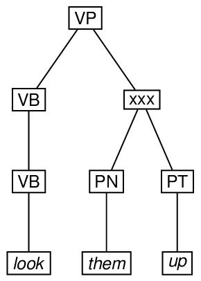
Finally, here is an example of an ordered tree, in which a particular node which ordinarily
would precede another is specified as following it. In the drawing, the xxx symbol indicates that the arc from VB to PT crosses the arc from VP to PN.
<leaf xml:id="GD-LOOK1" parent="#GD-VB2">
<label>look</label>
</leaf>
<leaf xml:id="GD-THEM1" parent="#GD-PN1">
<label>them</label>
</leaf>
<leaf xml:id="GD-UP1" parent="#GD-PT1">
<label>up</label>
</leaf>
<iNode xml:id="GD-VB2" parent="#GD-VB1"
children="#GD-LOOK1">
<label>VB</label>
</iNode>
<iNode xml:id="GD-PN1" parent="#GD-VP1"
children="#GD-THEM1">
<label>PN</label>
</iNode>
<iNode xml:id="GD-PT1" parent="#GD-VB1"
children="#GD-UP1" follow="#GD-PN1">
<label>PT</label>
</iNode>
<iNode xml:id="GD-VB1" parent="#GD-VP1"
children="#GD-VB2 #GD-PT1">
<label>VB</label>
</iNode>
<root xml:id="GD-VP1"
children="#GD-VB1 #GD-PN1">
<label>VP</label>
</root>
</tree>
TEI: Another Tree Notation⚓︎20.3 Another Tree Notation
In this section, we present an alternative to the method of representing the structure of ordered rooted trees given in section 20.2 Trees, which is based on the observation that any node of such a tree can be thought of as the root of the subtree that it dominates. Thus subtrees can be thought of as the same type as the trees they are embedded in, hence the designation eTree, for embedding tree. Whereas in a tree the relationship among the parts is indicated by the children attribute, and by the names of the elements root, iNode, and leaf, the relationship among the parts of an eTree is indicated simply by the arrangement of their content. However, we have chosen to enable encoders to distinguish the terminal elements of an eTree by means of the empty eLeaf element, though its use is not required; the eTree element can also be used to identify the terminal nodes of eTree elements. We also provide a triangle element, which can be thought of as an underspecified eTree, i.e. an eTree in which certain information has been left out. In addition, we provide a forest element, which consists of one or more tree, eTree, or triangle elements, and a listForest element, which consists of one or more forest elements. The elements used for the encoding of embedding trees and the units containing them have the following descriptions and attributes.
- eTree (embedding tree) provides an alternative to the tree element for representing ordered rooted tree structures.
value provides the value of an embedding tree, which is a feature structure or other analytic element. - triangle (underspecified embedding tree, so called because of its characteristic shape when
drawn) provides for an underspecified eTree, that is, an eTree with information left out.
value supplies a value for the triangle, in the form of the identifier of a feature structure or other analytic element. - eLeaf (leaf or terminal node of an embedding tree) provides explicitly for a leaf of an
embedding tree, which may also be encoded with the eTree element.
value indicates the value of an embedding leaf, which is a feature structure or other analytic element. - forest (forest) provides for groups of rooted trees.
- listForest provides for lists of forests.
Like the root, iNode, and leaf of a tree, the eTree, triangle and eLeaf elements may also have value attributes and label children.
To illustrate the use of the eTree and eLeaf elements, here is an encoding of the second example in section 20.2 Trees, repeated here for convenience.
<label>PP</label>
<eTree>
<label>P</label>
<eLeaf>
<label>with</label>
</eLeaf>
</eTree>
<eTree>
<label>NP</label>
<eTree>
<label>Art</label>
<eLeaf>
<label>the</label>
</eLeaf>
</eTree>
<eTree>
<label>N</label>
<eLeaf>
<label>periscope</label>
</eLeaf>
</eTree>
</eTree>
</eTree>
Next, we provide an encoding, using the triangle element, in which the internal structure of the eTree labeled NP is omitted.
<label>PP</label>
<eTree>
<label>P</label>
<eLeaf>
<label>with</label>
</eLeaf>
</eTree>
<triangle>
<label>NP</label>
<eLeaf>
<label>the periscope</label>
</eLeaf>
</triangle>
</eTree>
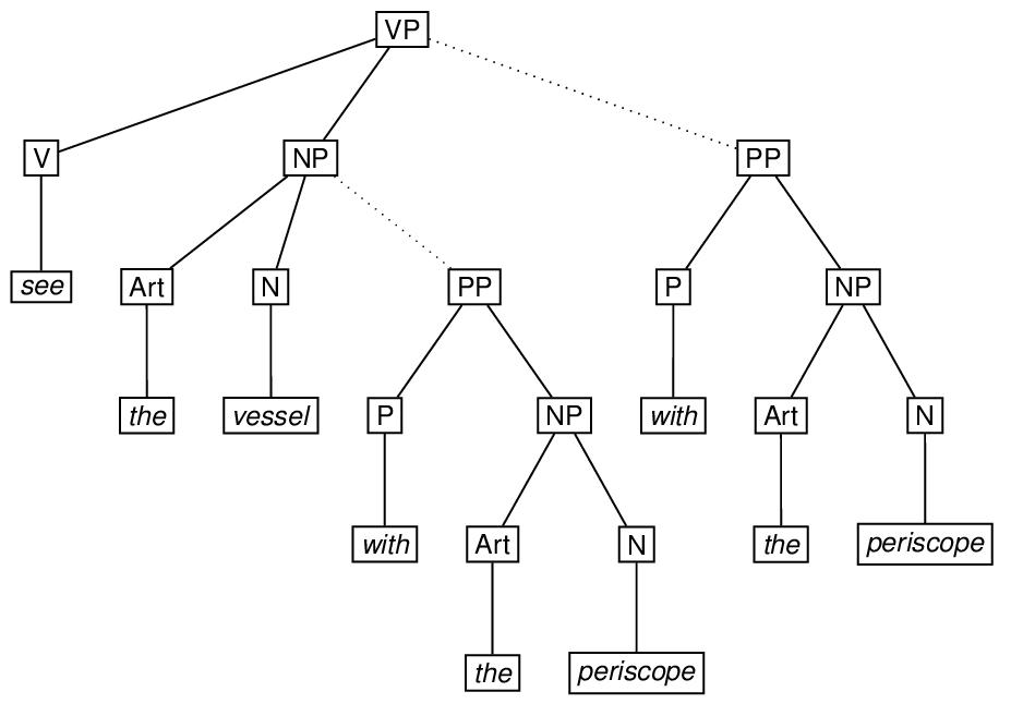
Ambiguity involving alternative tree structures associated with the same terminal sequence can be encoded relatively conveniently using a combination of the exclude and copyOf attributes described in sections 17.8 Alternation and 17.6 Identical Elements and Virtual Copies. In the simplest case, an eTree may be part of the content of exactly one of two different eTree elements. To mark it up, the embedded eTree may be fully specified within one of the embedding eTree elements to which it may belong, and a virtual copy, specified by the copyOf attribute, may appear on the other. In addition, each of the embedded elements in question is specified as excluding the other, using the exclude attribute. To illustrate, consider the English phrase see the vessel with the periscope, which may be considered to be structurally ambiguous, depending on whether the phrase with the periscope is a modifier of the phrase the vessel or a modifier of the phrase see the vessel. This ambiguity is indicated in the sketch of the ambiguous tree by means of the dotted-line arcs. The markup using the copyOf and exclude attributes follows the sketch.
<label>VP</label>
<eTree>
<label>V</label>
<eLeaf>
<label>see</label>
</eLeaf>
</eTree>
<eTree>
<label>NP</label>
<eTree>
<label>Art</label>
<eLeaf>
<label>the</label>
</eLeaf>
</eTree>
<eTree>
<label>N</label>
<eLeaf>
<label>vessel</label>
</eLeaf>
</eTree>
<eTree xml:id="GD-PPA" exclude="#GD-PPB">
<label>PP</label>
<eTree>
<label>P</label>
<eLeaf>
<label>with</label>
</eLeaf>
</eTree>
<eTree>
<label>NP</label>
<eTree>
<label>Art</label>
<eLeaf>
<label>the</label>
</eLeaf>
</eTree>
<eTree>
<label>N</label>
<eLeaf>
<label>periscope</label>
</eLeaf>
</eTree>
</eTree>
</eTree>
</eTree>
<eTree xml:id="GD-PPB" copyOf="#GD-PPA"
exclude="#GD-PPA">
<label>PP</label>
</eTree>
</eTree>
To indicate that one of the alternatives is selected, one may specify the select attribute on the highest eTree as either #GD-PPA or #GD-PPB; see section 17.8 Alternation.
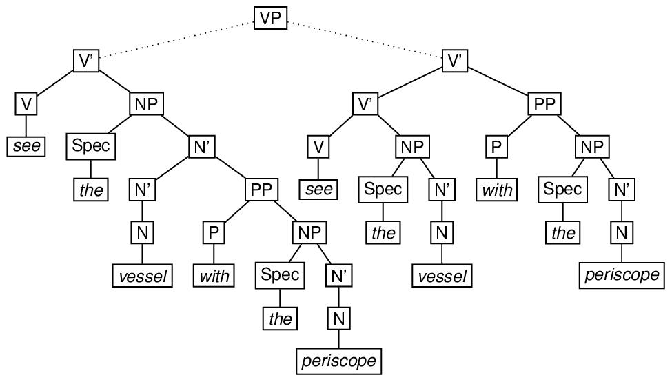
Depending on the grammar one uses to associate structures with examples like see the man with the periscope, the representations may be more complicated than this. For example, adopting a version of the X-bar theory of phrase structure originated by Jackendoff,90 the attachment of a modifier may require the creation of an intermediate node which is not required when the attachment is not made, as shown in the following diagram. A possible encoding of this ambiguous structure immediately follows the diagram.
<label>VP</label>
<eTree xml:id="VBARA" exclude="#VBARB">
<label>V'</label>
<eTree xml:id="VA">
<label>V</label>
<eLeaf>
<label>see</label>
</eLeaf>
</eTree>
<eTree>
<label>NP</label>
<eTree xml:id="SPEC1A">
<label>Spec</label>
<eLeaf>
<label>the</label>
</eLeaf>
</eTree>
<eTree>
<label>N'</label>
<eTree xml:id="NBAR2A">
<label>N'</label>
<eTree>
<label>N</label>
<eLeaf>
<label>vessel</label>
</eLeaf>
</eTree>
</eTree>
<eTree xml:id="PPA1">
<label>PP</label>
<eTree>
<label>P</label>
<eLeaf>
<label>with</label>
</eLeaf>
</eTree>
<eTree>
<label>NP</label>
<eTree>
<label>Spec</label>
<eLeaf>
<label>the</label>
</eLeaf>
</eTree>
<eTree>
<label>N'</label>
<eTree>
<label>N</label>
<eLeaf>
<label>periscope</label>
</eLeaf>
</eTree>
</eTree>
</eTree>
</eTree>
</eTree>
</eTree>
</eTree>
<eTree xml:id="VBARB" exclude="#VBARA">
<label>V'</label>
<eTree>
<label>V'</label>
<eTree xml:id="VB" copyOf="#VA">
<label>V</label>
</eTree>
<eTree>
<label>NP</label>
<eTree xml:id="SPEC1B" copyOf="#SPEC1A">
<label>Spec</label>
</eTree>
<eTree xml:id="NBAR2B" copyOf="#NBAR2A">
<label>N'</label>
</eTree>
</eTree>
</eTree>
<eTree xml:id="PPB" copyOf="#PPA1">
<label>PP</label>
</eTree>
</eTree>
</eTree>
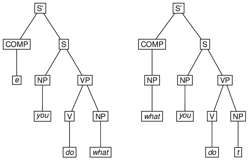
A derivation in a generative grammar is often thought of as a set of trees. To encode such a derivation, one may use the forest element, in which the trees may be marked up using the tree, the eTree, or the triangle element. The type attribute may be used to specify what kind of derivation it is. Here is an example of a two-tree forest, involving application of the ‘wh-movement’ transformation in the derivation of what you do (as in this is what you do) from the underlying you do what.91
<eTree n="Stage 1" xml:id="S1SBAR">
<label>S'</label>
<eTree xml:id="S1COMP">
<label>COMP</label>
<eLeaf xml:id="S1E">
<label>e</label>
</eLeaf>
</eTree>
<eTree xml:id="S1S">
<label>S</label>
<eTree xml:id="S1NP1">
<label>NP</label>
<eLeaf>
<label>you</label>
</eLeaf>
</eTree>
<eTree xml:id="S1VP">
<label>VP</label>
<eTree xml:id="S1V">
<label>V</label>
<eLeaf>
<label>do</label>
</eLeaf>
</eTree>
<eTree xml:id="S1NP2">
<label>NP</label>
<eLeaf xml:id="S1WH">
<label>what</label>
</eLeaf>
</eTree>
</eTree>
</eTree>
</eTree>
<eTree n="Stage 2" xml:id="S2SBAR"
corresp="#S1SBAR">
<label>S'</label>
<eTree xml:id="S2COMP" corresp="#S1COMP">
<label>COMP</label>
<eTree copyOf="#S1NP2" corresp="#S1E">
<label>NP</label>
</eTree>
</eTree>
<eTree xml:id="S2S" corresp="#S1S">
<label>S</label>
<eTree xml:id="S2NP1" copyOf="#S1NP1">
<label>NP</label>
</eTree>
<eTree xml:id="S2VP" corresp="#S1VP">
<label>VP</label>
<eTree xml:id="S2V" copyOf="#S1V">
<label>V</label>
</eTree>
<eTree xml:id="S2NP2" corresp="#S1NP2">
<label>NP</label>
<eLeaf corresp="#S1WH">
<label>t</label>
</eLeaf>
</eTree>
</eTree>
</eTree>
</eTree>
</forest>
In this markup, we have used copyOf attributes to provide virtual copies of elements in the tree representing the second stage of the derivation that also occur in the first stage, and the corresp attribute (see section 17.5 Correspondence and Alignment) to link those elements in the second stage with corresponding elements in the first stage that are not copies of them.
If a group of forests (e.g. a full grammatical derivation including syntactic, semantic, and phonological subderivations) is to be articulated, the grouping element listForest may be used.
TEI: Representing Textual Transmission⚓︎20.4 Representing Textual Transmission
A stemma codicum (sometimes called just stemma) is a tree-like graphic structure that has become traditional in manuscript studies for representing textual transmission. Consider the following hypothetical stemma:
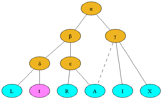
The nodes in this stemma represent manuscripts; each has a label (a letter) which identifies it and also distinguishes whether the manuscript is extant, lost, or hypothetical. Extant manuscripts are identified by uppercase Latin letters or words beginning with uppercase Latin letters, e.g., L, shown as aqua in this example; manuscripts no longer existing, but providing readings which are attested e.g. by note or copy made before their disappearance, are identified by lowercase Latin letters, e.g., t, shown as magenta in this example; hypothetical stages in the textual transmission, which do not necessarily correspond to real manuscripts, are given lowercase Greek letters, e.g., α and shown as gold in this example. The stemma shown above thus suggests that (on the basis of similarities in the readings of the extant and lost manuscripts) L and t share textual material that is not shared with other manuscripts (represented in this case by δ) even though no physical manuscript attesting this stage in the textual transmission has ever been identified.
Manuscripts are copied from other manuscripts. The preceding stemma represents the hypothesis that all manuscripts go back to a common ancestor (α), that the tradition split after that stage into two (β and γ), etc. Descent by copying is indicated with a solid line. According to this model, α is the earliest common hypothetical stage that can be reconstructed, and all nodes below α have a single parent, that is, were copied from a single other stage in the tradition.
This familiar tree model is complicated because manuscripts sometimes show the influence of more than one ancestor. They may have been produced by a scribe who checked the text in one manuscript of the same work whilst copying from another, or perhaps made changes from his memory of a slightly different version of the text that he had read elsewhere. Alternatively, perhaps scribe A copied a manuscript from one source, scribe B made changes in it in the margins or between the lines (either by consulting another source directly or from memory), and another scribe then copied that manuscript, incorporating the changes into the body. Whatever the specific scenario, it is not uncommon for a manuscript to be based primarily on one source, but to incorporate features of another branch of the tradition. This mixed result is called contamination, and it is reflected in a stemma by a dotted line. Thus, the example above asserts that A is copied within the ε tradition, but is also contaminated from the γ tradition.
The utility of a stemma as a visualization tool is inversely proportional to the degree of contamination in the manuscript tradition. A tradition completely without contamination (called a closed tradition) yields a classic tree, easily represented graphically by a stemma. An open tradition, with substantial contamination, yields a spaghetti-like stemma characterized by crossing dotted lines, which is both difficult to read and not very informative.
<label>δ</label>
<eLeaf type="extant">
<label>L</label>
</eLeaf>
<eLeaf type="lost">
<label>t</label>
</eLeaf>
</eTree>
<label>α</label>
<eTree type="hypothetical">
<label>β</label>
<eTree type="hypothetical">
<label>δ</label>
<eLeaf type="extant">
<label>L</label>
</eLeaf>
<eLeaf type="lost">
<label>t</label>
</eLeaf>
</eTree>
<eTree type="hypothetical">
<label>ε</label>
<eLeaf type="extant">
<label>R</label>
</eLeaf>
<eLeaf type="extant">
<label>A</label>
<ptr type="contamination"
target="#gamma"/>
</eLeaf>
</eTree>
</eTree>
<eTree xml:id="gamma" type="hypothetical">
<label>γ</label>
<eLeaf type="extant">
<label>I</label>
</eLeaf>
<eLeaf type="extant">
<label>X</label>
</eLeaf>
</eTree>
</eTree>
In any substantial codicological project, it is likely that significantly more data will be required about the individual witnesses than indicated in the simple structures above. These Guidelines provide a rich variety of additional elements for representing such information: see in particular chapters 11 Manuscript Description, 12 Representation of Primary Sources, and 13 Critical Apparatus.
TEI: Module for Graphs, Networks, and Trees⚓︎20.5 Module for Graphs, Networks, and Trees
The module described in this chapter makes available the following components:
- Module nets: Graphs, networks, and trees
The selection and combination of modules to form a TEI schema is described in 1.2 Defining a TEI Schema.
e and t denote special theoretical constructs (empty category and trace respectively), which need not concern us here.